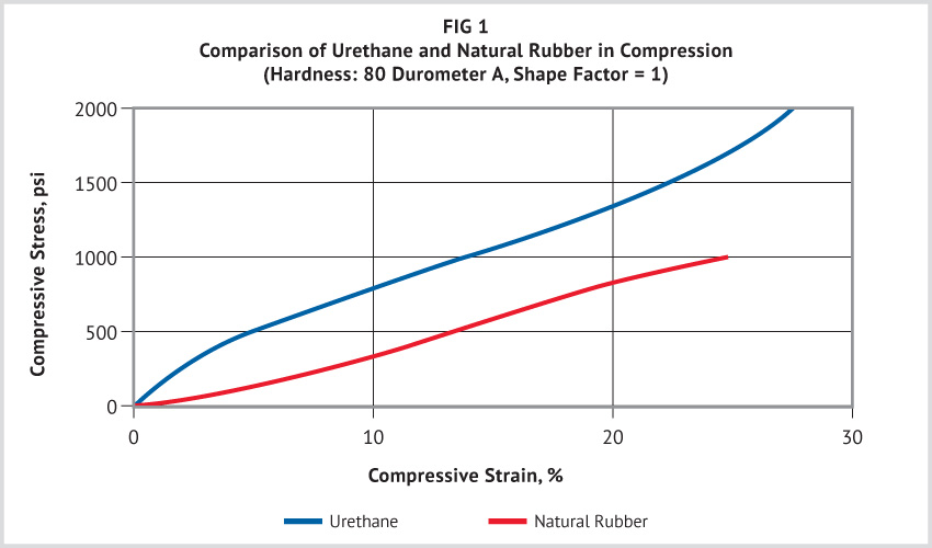
Urethane elastomers have a higher load-bearing capacity than do conventional elastomers of comparable hardnesses. This permits the design of smaller parts, with possible savings in weight and material costs. Compression-deflection curves for urethane and natural rubber vulcanizates of equivalent hardness (80 durometer A) are compared in Figure 1. This figure illustrates that urethanes can be loaded beyond conventional limits for rubber: 90A urethane has sustained short-term loadings of greater than 20,000 psi, and 95A urethane has been loaded to 68,000 psi without fracturing.
Effect of Load Surface Conditions
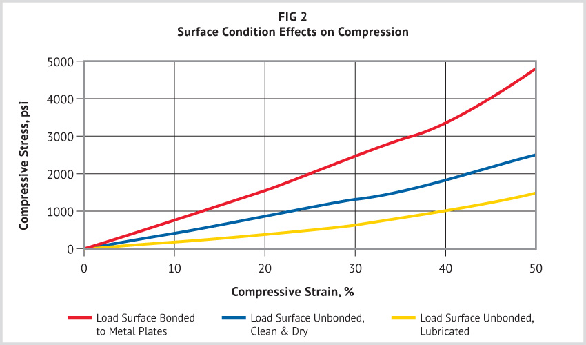
When an elastomeric piece is compressed between parallel plates, the surfaces in contact with the plates tend to spread laterally, increasing the effective load-bearing area. If this lateral movement of the surface is restricted, the compression-deflection behavior of the piece is changed. Restriction of lateral movement greatly stiffens the part.
Figure 2 illustrates this effect. A lubricated surface offers essentially no resistance to lateral movement. Lubrication at the metal-rubber surface may excessively strain the part because extreme deformation may occur. A clean, dry loading surface offers some resistance due to friction. But if the surface is bonded to the metal plates, no lateral movement is possible, thus ensuring reproducible compression values. These differences in contact surface result in three distinct compressive stress-strain relationships for the same piece of rubber. The load-bearing capability of urethane can be altered by a factor of 5 to 1 by changing only the surface conditions.
Effect of Shape
Shape factor is defined as the ratio of the area of one loaded surface to the total area of the unloaded surfaces that are free to bulge. Parts made from the same compound and having the same shape factor behave identically in compression, regardless of actual size or shape.
Effective use of compression-deflection data is dependent on having knowledge of the test conditions under which the data were observed. The values presented are customarily for normal room temperature and static or slow-speed operation. Other temperatures and dynamic loadings would change these values completely. Shape factors below 0.25 may permit buckling; therefore, higher shape factors should be used.
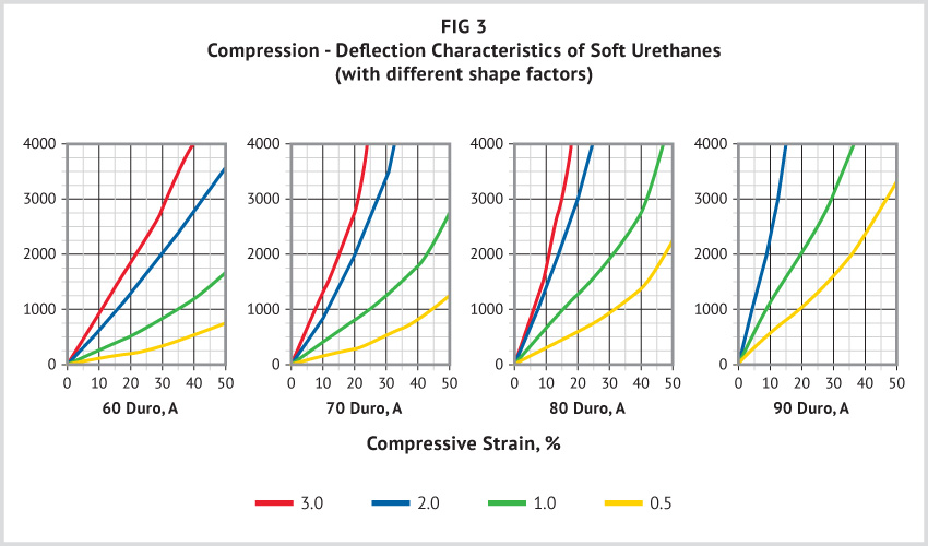
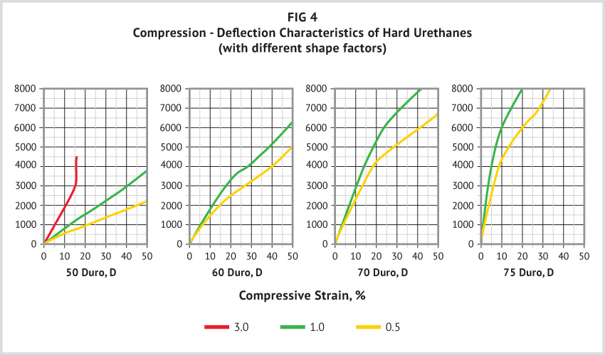
As shape factor increases, the unit load required to produce a given strain also increases. There is, however, no mathematical relationship between shape factor and compressive modulus; their relationship must be determined empirically. Figures 3 and 4 show compression-deflection curves for urethane that cover a range of hardnesses and shape factors. These curves were obtained with bonded surface. The compression-deflection characteristics of a fabricated item of a particular hardness may vary up to +/-10% from the curves shown. Deviations arise primarily from inaccuracies in measuring hardness of elastomer compounds.
Deformations are usually limited from 15% to 25%, which is the predictable straight line portion of the shape factor curves. Deformations above 25% impose higher stresses, inducing much higher set, and increasing creep, in the part.
Use of Compression Stress-Strain Curves in Design
The following examples show how the compression stress-strain curves can be used in the design of urethane parts. Shape factor for blocks and cylinders is calculated as follows:
For rectangular-shaped prisms
Shape factor = 1w / (2t (1+w))
where l = length, w = width, t = thickness, d = diameter, h = height
For discs and cylinders
Shape factor = d / (4h)
These relationships are limited to pieces for which all of the following conditions exist:
- Parallel loading faces
- Thickness is not more than twice the smallest lateral dimension
- Loading surfaces are restrained from lateral movement
Example 1
Problem
Assume a pad 8 inches square by 1 inch thick, made of 70 durometer A. How much will the pad deflect under 1000 psi compression stress?
Solution
(a) The shape factor of the piece is:
one loaded surface area / total free bulge area = (8 x 8) / ((2 x 1) x (8+8)) = 64/32 = 2
(b) In Figure 3 we find that the compressive stress-strain curve of a 70A durometer urethane part with a shape factor of 2 crosses the 1000 psi stress abscissa at 11% strain. Therefore, the pad will deflect 11% of one inch, or .11 inch.
Example 2
Problem
What happens if the pad thickness is doubled in Example 1?
Solution
(a) Shape factor of the piece is now: (8 x 8) / ((2 x 2) x (8+8)) = 64/64 = 1
(b) From Figure 3, the compressive strain at 1000 psi stress for a 70 durometer A part with a shape of 1 is 25%. In this case the pad will deflect 25% of two inches, or 0.50 inch. (Note: In practice, parts made of conventional elastomers are generally designed so that compressive strain does not exceed 15%.)
Example 3
Problem
Assume a pad that is one inch square by one-half inch thick and bears a compressive load of 2500 lbs. The pad may not deflect more than 0.05 inches because of space limitation. What hardness of urethane vulcanizates should be specified?
Solution
(a) Shape factor of the piece is: (1 x 1) / ((2 x 1/2) (1 +1)) = ½ = 0.5
(b) Unit compressive stress is: 2500 / (1×1) = 2500 psi
(c) Compressive strain is: 0.05 /0.5 x 100 = 10%
(d) On scanning the compressive stress-strain curves, we find in Figure 4 that vulcanizates which are 60D hard or harder will bear a compressive stress of 2500 psi with 10% or less deflection.
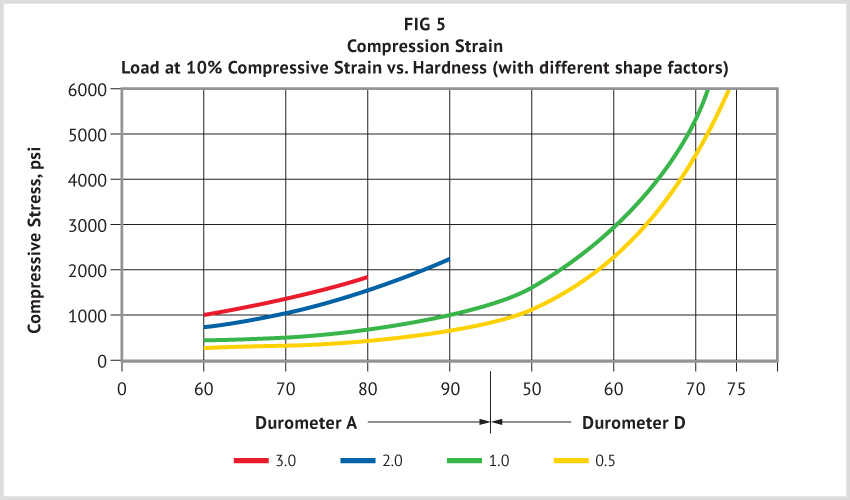
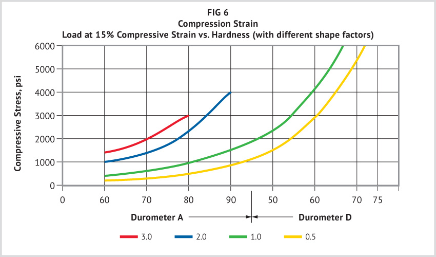
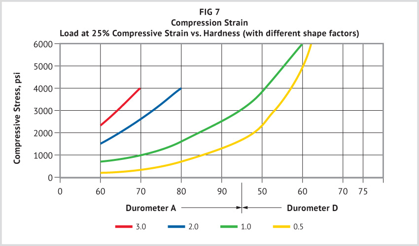
As a general rule, the harder the elastomer, the greater its load-bearing capacity. The manner in which load-bearing properties of urethane change with hardness at various deformations is shown in Figures 5 through 7.
Access more articles in our Urethane Knowledge Center.


