Defining Draft in Injection Molded Parts
Draft is a taper, or angled face, that is added to the design of injection molded parts to assist with removal of the parts from the molds. Draft is added in the pull direction of the mold or slide component. Proper draft angles in the design of the part help avoid issues such as poor cosmetic finishes, cracking of the plastic at ejection, warping, scuffing, and scraping. Included here is an image demonstrating how draft can affect a part.
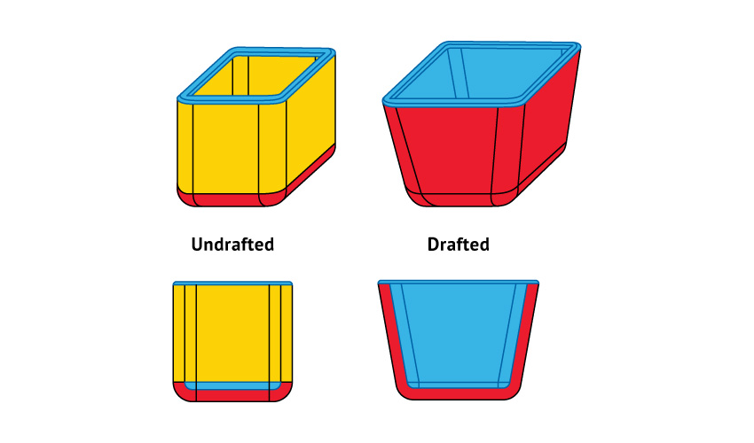
An undrafted (left) versus drafted (right) cube.
Importance of Adding Draft Early in the Design Phase
It is important to add draft to the design early in the prototyping and modeling phase. Planning for draft from the beginning of the production process will help avoid redesigns, with their associated costs and losses in lead time, and part issues at production, which come with additional prototype development costs or mold change costs. Draft angles can also affect fitment of parts in assemblies, so it is crucial to understand these fitment effects early in the design phase, before the plan is finalized. Also important to keep in mind is that 3-D printing and machining do not require draft on sidewalls of parts.
Draft Considerations
In some cases, not all elements of a tool will require the same size draft. Depending on the specific features of the part design, each portion may require different levels of draft. Material selection, ejection layout, shrink rate, wall thickness, finish/texture, wall depth, and manufacturer capabilities all come into play.
Industry standards can help designers start down the right path of draft design considerations. A few examples are listed here. It is recommended to add as much draft as possible for the design of molded parts—a general rule of thumb is 1 degree of draft per 1 inch of cavity depth, but that can change depending on the specific feature and chosen surface finish for the application. Try following these general guidelines:
- 0.5 to 1 degree of draft on all vertical faces is strongly advised. This includes faces that are located on a movable slide as well.
- 1 to 2 degrees works very well for light EDM and bead-blasted textures.
- 3 degrees is minimum for metal-on-metal shutoff.
- 3 degrees is required for light texture (MT1101, MT11020).
- 5 or more degrees is required for heavy texture (MT11050).
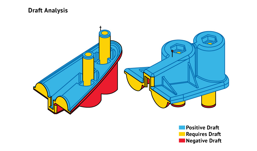
DFM Analysis Helps Mitigate Draft Issues
Design for Manufacturability (DFM) analysis is a great way to catch draft and design issues early in the product development phase. DFM analysis is a service that Molded Dimensions Group (MDG) provides for every mold project. Using a 3-D CAD model, our team of engineers interrogates the design for any potential manufacturability downfalls. With this analysis, our customers receive a detailed list of improvements needed in order to proceed with manufacturing the mold. This process includes analysis of thickness, mold flow, draft, and more. As such, the exercise is useful in preventing molding issues at production of the part.
With over 30 years of molding experience in plastics, the design team at MDG would be delighted to help guide your product through the design process. Please reach out to our team with questions, or to get started.
Access more articles in our Plastic Knowledge Center.